
In the recent years building engineering has come a long way and designing a building that lasts more than 50 years isn't uncommon, yet sometimes we come across structures that start showing signs of decay even at the start of their service life. This may be caused due to either "bad design" (weather conditions may not have been taken into account resulting in quick corrosion and related cracking in extreme weather situations) or "Bad supervision" when working on the design on the ground (lack of proper supervision and skill may cause the end product to be lacking in structural elements or connections. of the above, chances of the latter occurring on a structure you are getting made are higher, since the design passes through many professionals before it lands on the clients lap so it usually has been checked multiple times, by professionals and authorities. this brings us to bad supervision in civil jobs, which may also be translated to no supervision at all.Typically, the building construction industry, which is very unorganised in India becomes even more unorganised in rural India, which is where we encountered the present building, due to which buildings are constructed with low technical knowhow of the modern structural systems and since traditional construction systems have far been abandoned the product comes out to be of very low quality.
the present building in question is an institutional building of a single storey and a typical rectangular plan.


In the structure, four types of cracking has been recognised in the walls. apart from these cracking is present in the slab as well. the location of each of the cracks can be found in the plan above, each of the cracks are present in the superstructure (the walls, beam or slab) but none was found in the floor or below. this observation clearly rules out the possibility of the occurrence of the cracks due to settlement of the foundation.


1. Diagonal Cracks at openings due to absence of Lintels: a lintel is a short beam type structural element that has a better load bearing capacity than the opening and wall materials and can bear the load of that part of the wall that is above the opening. if the presence of lintel failure or absence of a lintel altogether, diagonal cracks appear originating usually from the corner of the openings. This is because of a discontinuity present in the walls load bearing capacity due to the opening. the cracking pattern is illustrated in the diagram above, where this type of cracking is marked with 2.


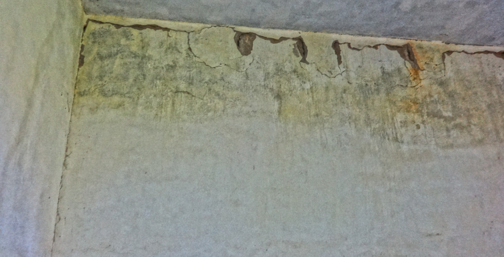


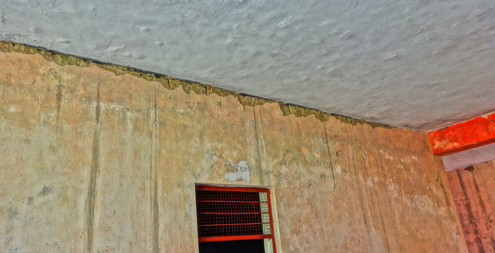


2. Heavy cracking due to slab (simply supported, continuous, supported without fixity), creating upward deflection at supports: excessive cracking has occurred horizontally at the top of all the walls which support directly the loads of the slabs above without beams to distribute the loads. on top of that, large spans of the slab cause excessive deflection and having not much vertical load above the support to resist uplift of the slab at the support and movement of the of the slab is restrained on one side.

This deflection causes excessive horizontal cracking at the junction of the wall and the slab, and since there is no fixity at the junction, cracking occurs. Brittle nature and low tensile strength of masonry makes it highly susceptible to cracking even in smaller stresses. smaller cracking defects spread throughout the surface of the walls are frequently associated with incompatibility between structural components (e.g.
excessive deformation of concrete slabs or beams, aggravated by long term effects),
expansion/shrinkage of masonry materials (e.g. clay or cement based elements) and
thermal movements (masonry and building structure).


3. Cracking on walls due to transfer of loads and moment through beams: The biggest classrooms in the building are the ones in the right corner of the plan, which have a slab supported by three beams equidistant from each other, each 1 ft X1.5ft. The load of the beams is directly supported by the walls only, which also bear the moment transferred by the slab to the beams. This has resulted in diagonal cracking at the points of junction between the walls and beams. The walls of the bigger classrooms have also gone through expansion cracking at the corners. The renovation at the corners had already begun before our visit and the wall had been removed in that part.

Due to the roof slab being one monolithic slab (rather than being cast in parts with expansion joints) it has cracked in multiple places, now becoming two or three separate slabs which are in need of expansion joints to prevent expansion and seepage through cracks.During the monsoons ponding and other water related problems occur on the slab due to improper levelling as well.
Conclusion
The above case study presents one example of the effect of the lack of proper design and construction supervision has on buildings. Buildings built without design of proper structural load bearing systems and other material maintenance systems do not last even a fifth of their design life. This can be demonstrated through this buildings example as it was built in 2010 and before the end of 10 years needs a proper rehabilitation.
Apart from basic maintenance of the walls plaster and paint etc, structural retrofitting will also be required to increase the life of the structure. We suggest adding structural elements where missing. the building, as of now, is supported on beams and walls, we suggest adding columns to support the beams and different sizes of beams where the slab is directly supported on the walls. the following steps may be followed to complete the rehabilitation in order
the refurbishment needs to be carried out in phases starting with the largest slabs from behind and coming to the front. before any chipping of walls takes place, the slab needs to be supported firmly in place through a shuttering system.
after the shuttering support system is ready, the wall systems can be chipped at the corners and at places where columns are needed, the reinforcement can be laid in place and concrete can be poured upto a level of the slab.
after the columns get casted and the shuttering removed, the walls may be chipped at the top and beams may be casted. The beam sizes may vary according to the span.
Although the refurbishment will be an arduous process and will take time, this can be considered an easier refurbishment since the property is part of a bigger property of the same client (this will result in easier working and space for the pouring of the concrete for the beams and the columns) and that the building is a single storey building so care need not be taken to the effects on the upper storeys when lower storeys are being refurbished.
Comments